Arduino Pro Micro
The SparkFun Pro Micro is an ATmega32U4 board in a Pro Mini footprint. The 32U4 has USB built into the microcontroller, so there is no separate USB-serial chip — the board can present itself as a keyboard, mouse, or serial device directly.
Pinout
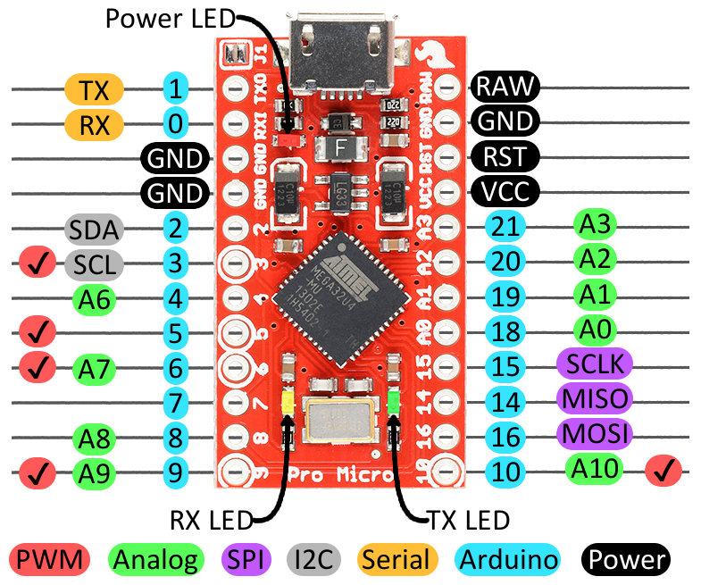
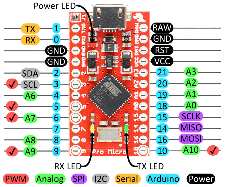
Source: SparkFun — graphical datasheet from the Pro Micro & Fio V3 Hookup Guide (original image). SparkFun tutorials are CC BY-SA 4.0.
Broken-out pins
Left side, top to bottom:
| Pin | Alternate functions |
|---|---|
| 1 | TXO (Serial1 transmit) |
| 0 | RXI (Serial1 receive) |
| GND | |
| GND | |
| 2 | SDA (I²C data) |
| 3 | SCL (I²C clock), PWM |
| 4 | A6 |
| 5 | PWM |
| 6 | A7, PWM |
| 7 | |
| 8 | A8 |
| 9 | A9, PWM |
Right side, top to bottom:
| Pin | Alternate functions |
|---|---|
| RAW | Unregulated supply input, ahead of the regulator |
| GND | |
| RST | Reset, active low |
| VCC | Regulated rail — output, or input if bypassing the regulator |
| 21 | A3 |
| 20 | A2 |
| 19 | A1 |
| 18 | A0 |
| 15 | SCLK (SPI clock) |
| 14 | MISO |
| 16 | MOSI |
| 10 | A10, PWM |
Summary of what that leaves available:
- Digital I/O: 0–10, 14–16, 18–21 (18 pins)
- PWM: 3, 5, 6, 9, 10 (5 pins)
- Analog in: A0–A3 on 18–21, plus A6–A10 on 4, 6, 8, 9, 10 (9 pins)
- I²C: SDA on 2, SCL on 3
- SPI: SCLK 15, MISO 14, MOSI 16. Chip select is up to you — the 32U4's hardware SS is on the same line as the RX LED and is not broken out.
Specifications
| MCU | ATmega32U4 |
| Variants | 5 V / 16 MHz and 3.3 V / 8 MHz |
| Flash | 32 KB, ~4 KB consumed by the bootloader |
| SRAM | 2.5 KB |
| EEPROM | 1 KB |
| USB | Native (micro-USB on current revisions) |
RAW input | Regulator input; 5 V boards tolerate roughly 5–12 V |
| Arduino board type | SparkFun Pro Micro (5 V or 3.3 V — pick the right one) |
Notes and gotchas
- Two Serial objects.
Serialis the USB CDC connection to the host;Serial1is the hardware UART on pins 0 and 1. They are not the same, and code written for an Uno that expectsSerialon the TX/RX pins will need changing. - The serial port disappears on reset. Because USB is implemented by the same chip running your sketch, the port enumerates and de-enumerates across resets and uploads. Sketches that hang or reconfigure USB can make the board hard to program.
- Bootloader entry: tap reset twice quickly to force an eight-second bootloader window, then upload. This is the recovery path when a sketch has made the board unreachable.
- Pick the right variant in the IDE. Selecting 5 V when the board is 3.3 V (or vice versa) gives a working upload with a clock off by 2×, which shows up as garbled serial and wrong timing rather than an obvious failure.
- 3.3 V boards run at 8 MHz. Not a separate consideration from the above — the clock rate is tied to the variant, so any timing-critical code has to know which board it is on.
References
- Pro Micro & Fio V3 Hookup Guide — SparkFun's own documentation, source of the pinout diagram above
- ATmega32U4 datasheet — Microchip, for register-level detail