The generic 16-character × 2-line character LCD. Almost every module sold under this description is driven by a Hitachi HD44780 or a pin- and command-compatible clone (Samsung KS0066, Sitronix ST7066), which is why the same wiring and the same library work across parts from different vendors.
Pinout
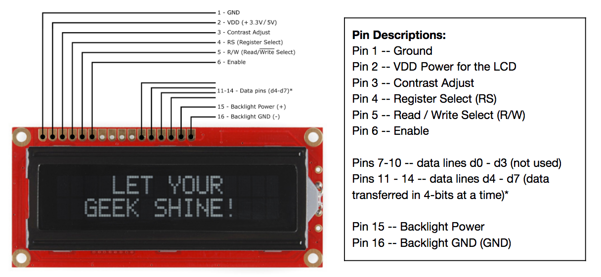
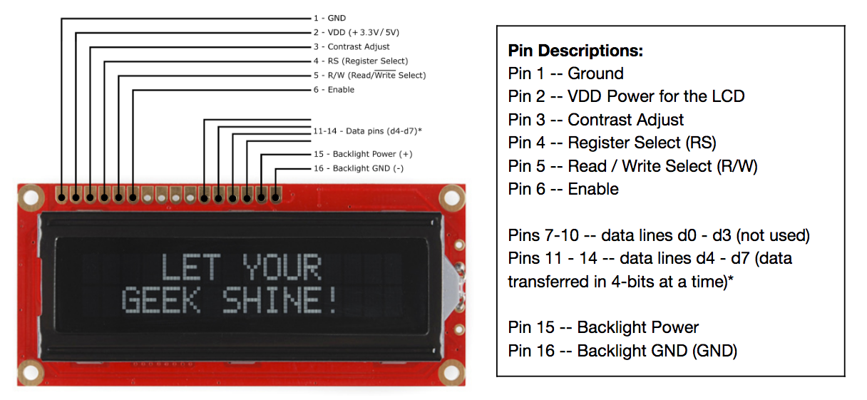
Source: SparkFun — Basic Character LCD Hookup Guide (original image). SparkFun tutorials are CC BY-SA 4.0.
Pin assignments
| Pin | Name | Function |
|---|---|---|
| 1 | VSS / GND | Ground |
| 2 | VDD / VCC | Logic supply, usually 5 V |
| 3 | V0 / VEE | Contrast bias — wiper of a trimpot |
| 4 | RS | Register select: low = command, high = data |
| 5 | R/W | Low = write, high = read |
| 6 | E | Enable — data latches on the falling edge |
| 7 | D0 | Data bit 0 — 8-bit mode only |
| 8 | D1 | Data bit 1 — 8-bit mode only |
| 9 | D2 | Data bit 2 — 8-bit mode only |
| 10 | D3 | Data bit 3 — 8-bit mode only |
| 11 | D4 | Data bit 4 |
| 12 | D5 | Data bit 5 |
| 13 | D6 | Data bit 6 |
| 14 | D7 | Data bit 7, doubles as the busy flag |
| 15 | A / LED+ | Backlight anode |
| 16 | K / LED− | Backlight cathode |
The SparkFun diagram above marks pins 7–10 "not used" because that guide wires the display in 4-bit mode. They are D0–D3 and are only idle in that mode; in 8-bit mode they carry the low nibble.
RGB-backlight variants have 18 pins — pins 16, 17, and 18 become the separate red, green, and blue cathodes.
Minimum wiring
Six microcontroller pins, the usual arrangement:
| LCD pin | Goes to |
|---|---|
| 1 (VSS) | GND |
| 2 (VDD) | +5 V |
| 3 (V0) | 10 kΩ trimpot wiper; trimpot ends to +5 V and GND |
| 4 (RS) | Any digital pin |
| 5 (R/W) | GND |
| 6 (E) | Any digital pin |
| 11–14 (D4–D7) | Four digital pins |
| 15 (A) | +5 V through a series resistor |
| 16 (K) | GND |
Tying R/W to ground makes the display write-only, which costs nothing in practice — the busy flag is the only reason to read from it, and library code just waits out the worst-case timing instead. That saves a pin.
In the Arduino LiquidCrystal library this is:
#include <LiquidCrystal.h>

// LiquidCrystal(rs, enable, d4, d5, d6, d7)
LiquidCrystal lcd(12, 11, 5, 4, 3, 2);

void setup() {
  lcd.begin(16, 2);       // columns, rows
  lcd.print("hello");
}
Notes and gotchas
- The backlight needs a series resistor. Pin 15 goes to a bare LED anode on many bare modules — no onboard current limiting. Connect it straight to 5 V and you cook the backlight. Something in the 100–220 Ω range is typical; check the specific module's datasheet, because some do include a resistor and adding another just dims the display.
- Blank display with the backlight on is usually contrast, not code. Pin 3 needs to sit near the bottom of its range. If a trimpot sweep produces no visible characters at any setting, then suspect wiring.
- Line 2 is not contiguous with line 1. DDRAM for a 16x2 starts line 1 at address
0x00and line 2 at0x40, so writing past column 16 does not wrap to the second line — it runs into unseen address space. Uselcd.setCursor(0, 1)rather than relying on wrapping. - Contrast bias may want a negative rail. Standard TN modules bias fine against ground, but some extended-temperature parts need V0 below ground, which a plain trimpot between VDD and GND cannot supply.
- 3.3 V logic is not the same as a 3.3 V module. HD44780 modules are specified for 5 V logic and 5 V LCD bias. A 3.3 V microcontroller can usually drive the control and data lines directly since they are inputs and the thresholds happen to work, but the module itself generally still wants 5 V on VDD to get usable contrast. Modules explicitly sold as 3.3 V exist; do not assume a given one is.
- An I²C backpack trades pins for a chip. PCF8574-based adapter boards solder onto the 16-pin header and reduce the interface to SDA, SCL, and power. Cheap and popular, and it costs six pins' worth of wiring, at the price of a slower interface and a second address to keep track of.
References
- Basic Character LCD Hookup Guide — SparkFun, source of the pinout diagram above
- HD44780U datasheet — Hitachi, the authority on command set, timing, and DDRAM/CGRAM addressing
- Arduino
LiquidCrystalreference — library API